
")


Huawei has introduced variety of Unified Storage Systems in market. OceanStor T series unified storage (T series) is the most popular product in enterprise market. T series provides converged architecture, protocols, and platforms. With leading performance, unique features, and efficient resource utilization, the T series offers comprehensive high-performance
solutions. Maximizing customer ROI, the T series applies to OLTP/OLAP databases, high performance computing (HPC), digital media, Internet-based operating, central storage, backup, disaster recovery, and data migration.
Out of the box configuration of Huawei OceanStor T series
As for the tutorial, we will use the smallest unit of the Oceanstor product line: S2200T as a demo. All T series models support same type of configuration. The S2200T is the smallest one as hardware solution, but it has standard SAN capabilities and, more important, it uses the same management console as the bigger ones: the ISM (integrated Storage Management)

Step 1: Assigning the management IP Addresses

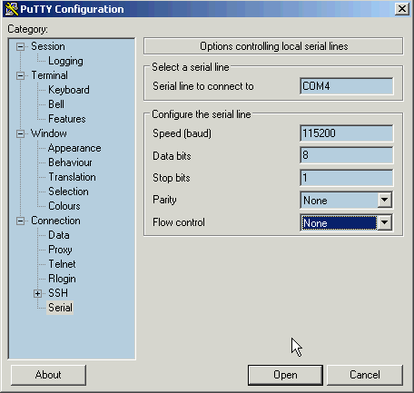
To begin with this task, we have to start working with an old IT technology: RS-232 serial communication.
At first, we have to use the serial cable supplied with storage.
In support of the serial cable, either we have to use a PC with an old RS-232 port, or an actual laptop equipped with a converter like the one pictured here: USB to RS-232.
After having joined the converter to the serial cable, use the other end of the latter to plug the RJ-45 connector to the SAN, in the port bearing the following symbol: |O|O|. (that is positioned towards the middle of the rear panel, like in the following picture).
There are two ports of this kind (CONSOLE), one for each controller: you can use either one or the other indifferently, since you can use one to configure the other, as you like.

Now let’s turn to the activities to be performed on the PC.
We will use the freeware PUTTY as terminal emulator.
Training on PUTTY is not our purpose, however I will list the necessary settings required by the SAN, so you can use them on your preferred terminal emulator.
Briefly, we have an 8n1 at 115200 bps without flow control.
The default credentials are: user=admin, password=Admin@storage
If everything is typed correctly, the storage will reply with the welcome screen in the picture here on the right.
Now we are ready to enter the management IP addresses!

The command that we will use is chgctrlip (ie: Change Controller IP)
We can see here an example of the default syntax by typing :
help -c chgctrlip
The highlighted line is our example, so we just have to customize the IP parameters to match our environment, and remember to set the appropriate address on each controllers: a and b.
The controller is simply identified by the character between -c and -ip.
Here’s how it answers to the actual command.


At this point, let’s verify that the address have been acquired correctly and leave.
Our command is showctrlip.

Finally, if we can ping the SAN from our computer or our server, we can say we did everything correctly.
As a double check, we can try and access via HTTP, and here is what we get: the installation prompt of the ISM.

Step 2: Configuring the i-SCSI communication protocol
This activity is divided into 4 main topics:
- IP address configuration on the SAN i-SCSI port
- Configuration of the dedicated network card on the application server (Windows)
- Configuration of the i-SCSI Initiator, still on the application server
- Verify that the Initiator is recognized by the i-SCSI Target (SAN)
We assume that a very simple network configuration has been deployed between servers and SAN: a simple direct network cable on a dedicated IP subnet, or through a switch, essentially without routing. In case of more parallel i-SCSI connections, the most simple way is to apply a not routed subnet to each connection pair.
If the link is routed, or the subnet is “busy” from other traffic, you can get a performance degradation that, in a so delicate and otherwise simple environment, is not desirable.
To access OcenStor ISM in web browser, you need Java ver. 7 plugin. Without Java plugin you won’t be able to access ISM
 In figure one the four controller A ports are highlighted, with every detail of the port H2, so as we can see in Device Info by ISM. In total, we have 8 ports that can work in a variety of configurations, including redundancy and aggregation of flows.

The summary of the i-SCSI ip parameters, and the ability to configure them, are available in PORTS by ISM, under the tab iSCSI-Host-Ports. Figure 2 shows us only the first 4 interfaces, all presenting the status of link-down as they are not yet connected to the application server.

Now let’s pass to the server configuration (Windows). As we previously announced, and is better to reserve one or more interfaces to i-SCSI only protocol. Figure 3 shows us just one of these interfaces already with optimized protocols: disable all but the only one we need: IPv4


Figure 4 shows the detailed configuration of IPV4: it is a classic static IP configuration, strictly reduced to the minimum necessary values, so without a dafault gateway and without DNS, since the traffic of this interface should not roam the internet and must not have other functions. All in all, the presence of more default gateways, in a windows environment, is not desirable.
 Once configured the IP on both sides of the connection, we can verify it, by, for example, a simple PING command from server to SAN.
At this point, the IP configuration of both endpoints and is completed and verified: let’s pass to real i-scsi management.
The tool provided to us since a few of Windows operating system versions, is iSCSI Initiator. As shown in Figure 6, is located between the administration tools for Windows 2012, and essentially has not changed compared to that of Windows 2008 and Windows 2008 R2

Once launched, move to the Configuration tab on the far right: This page shows the default name with which this server is presenting itself to the rest of the i-SCSI worls, and, frankly, it is a set of long words, difficult to understand and difficult to manage (remember that this name must appear on ISM that, notoriously, holds data in columns in very tight spaces).

Can be very helpful to set a name that helps identify the server from the remote side of the connection (i-SCSI target of SAN). Figure 8 exhibits a much explanatory example.

Now that we have verified our SAN is reachable, let’s connect it.
In order to do this, let’s click the TARGETS tab on the i-SCSI Initiator: here simply type the IP address of our i-SCSI counterpart (the SAN), and then click Quick Connect (Figure 9).


After a few seconds we get a response equivalent to what is shown in Figure 10: not very clear but you can recognize that our Huawei Oceanstor is responding.
Returning to the Targets tab and expanding the column appropriately, we can verify that the IP we wanted to contact is online and responsive.
In case of multiple connections, you have to repeat the procedure trying all the IP remote targets, for which the Figure 11 will show a row for each connection.

Now the last verification: the SAN has to be aware of our connection: this is visible in the Initiators in ISM.
The Identifier column shows just the name of our server, clear and understandable, as set in Figure 8.

After applying above configuration you would be able to communicate Huawei SAN to the servers. Now simply add required storage to the servers.


